
Let's extract firmware from IoT devices

You wanna start to look for goodies inside a smart camera, or just having fun to see if your Wi-Fi router is speaking to a foreign country?
My name is Adrien Lasalle , a hardware hacker/maker specialist and in this article I'll show you the basic methods that work for 85% of the IoT you could find everywhere to extract the Firmware and play with it.
Why should you extract firmware?
The firmware is your primary target when you start a Hardware Hacking journey on a new device. Everything lives in that binary file: Web server, TLS stack, hardcoded credentials, custom scripts from the dev team, etc. You cannot audit what you cannot read, so the first job in any device assessment is getting the firmware off the device, into your hands.
What the extraction is going to unlock:
Static analysis: Disassemble the binaries, find logic flaws and various bugs without touching the device itself.
Secret Hunting: Hardcoded passwords, API tokens, private certificates and backdoors users. Anything plaintext would be visible.
Emulation: Once the filesystem is in your hands, you can run services under QEMU and fuzz them off-device in a controlled and fast environment.
Bug Bounty & CVE research: Looking for a reward in a Bug Bounty program, most of these IoT devices have one and you could get credits in a CVE release.
Privacy: You want to audit a device and be sure it’s not sending data to a remote IP you can't control.
The method you reach for depends on what the vendor exposes. Start with the laziest option that works and escalate if you have to.
Now you know what you have to do :

Disclaimers
Before hacking everything though, some things to consider !
Electricity
Working on powered boards risks shorting traces, destroying the target, or damaging your equipment. Know your voltages before connecting anything, a 5V programmer on a 1.8V flash kills the chip. Disconnect power before probing, don’t bridge pins you didn’t mean to, and never work on mains-connected equipment (anything plugged into a wall without an isolating transformer) unless you know exactly what you’re doing. Lithium cells can vent or catch fire if punctured or shorted.
Soldering
Soldering irons reach 300-400°C and cause serious burns. Work in a ventilated space, flux fumes and leaded solder are harmful to inhale, and wash your hands afterward. Hot air rework can send solder balls flying; wear eye protection. Desoldering flash chips risks lifting pads and permanently damaging the board, so practice on scrap before touching a target you care about.
Ethical Hacking
These techniques are for devices you own or are explicitly authorized to test. Extracting and analyzing firmware without permission can violate computer-misuse law (CFAA in the US, the Computer Misuse Act in the UK, and equivalents elsewhere), anti-circumvention law (DMCA 1201 when you bypass protections), and the device’s terms or warranty. Authorization is specific: owning one unit doesn’t authorize attacking a vendor’s cloud, other users’ devices, or production infrastructure. Security research has real legal protections in some jurisdictions, but they are narrow and conditional, know yours before you start. If you’re testing for a client, get the scope in writing
Method 1: Direct Download from Vendor
Always try this first. A simple Google search is free and non-destructive, it often gives you a clean image in minutes. Many vendors publish update images on their support site, and some leave old versions sitting on predictable URLs.
Where to look:
The product's support/download page, grab every version, not just the latest. Older builds carry bugs that were later patched.
A community GitHub repo, some people keep track of the firmware updates on their own, and they share the binaries to everyone. Example with Tapo C200 firmware

Looks easy? There is a catch.
Downloaded images can be encrypted, compressed or packed in a vendor container. You can use binwalk to start your triage.
Identify sections, compression and filesystems
binwalk firmware.bin Entropy scan : A flat ~8.0 line means encrypted/compressed
binwalk -E firmware.bin Attempt extraction of known filesystems
binwalk -e firmware.bin High, featureless entropy across the whole file means you are looking at encryption and this method dead-ends unless you can find the key (often in the bootloader or the mobile app). A stepped entropy profile with recognizable headers means it is only compressed, and binwalk will usually carve the filesystem straight out. When the download is a dead end, go to the hardware.
Method 2: Get the API endpoints
If the device won't hand you the image directly, make it fetch one and grab it in transit. Trigger a firmware update from the companion app or admin panel while sitting between the device and the internet. The update request leaks the exact download URL, and the image itself often flies past in cleartext
Put yourself in the path, a rogue Access Point, ARP Spoofing or simply point the device's gateway and DNS at your box. Then sniff:
# Plain HTTP: Catch the URL and the binary as they go past
sudo tcpdump -i eth0 -A -s 0 'tcp port 80' | grep -iE 'firmware|update'
For HTTPS, run a transparent proxy. IF the device pins its certificate the handshake fails and you learn only the hostname, if it does not pin (Common on cheap IoT) you get the full URL and payload.
mitmproxy --mode transparent --showhostTrigger the update, watch the flow, and save the response body: that is your firmware. A surprising number of devices skip TLS entirely for updates, which makes this the fastest path when the static download is gated or obfuscated.

Intercepting companion APP (Android)
The companion app often requests the firmware manifest or image itself. You could check the source code of the android apk, looking for any endpoints that could lead to the firmware update URL.
If it's not possible, you can put Burp Suite between the app and the internet, and use Frida to defeat certificate
pinning when the app refuses your CA.
More information here: Configuring an Android device to work with Burp Suite
Method 3: Dump SPI Flash

When the download is encrypted or absent, you'll have to knock at the door of the chip directly. Most IoT devices keep their firmware on an external SPI NOR flash, an 8-pin SOIC package (often a Winbond W25Q, Macronix MX25, or GigaDevice GD25) sitting next to the SoC.

Read the voltage before you connect anything
This is the step that kills chips. The common black CH341A modules drive their SPI lines at 5V, but nearly every SPI NOR flash in a modern device runs at 3.3V, and some at 1.8V. Hooking a 5V programmer to a 1.8V part can destroy the flash, the SoC, or both.

Before connecting:
Read the flash part number off the chip and pull its datasheet. Confirm its operating voltage (VCC).
Assume the black CH341A is 5V on the data lines until you have proven otherwise with a meter.
For 3.3V parts, either modify the module (the well-known 3.3V mod that re-routes the regulator) or use a programmer with a proper level shifter / selectable voltage. For 1.8V parts you must use a level shifter or a 1.8V-capable programmer, there is no safe shortcut.
More information : CH341A Important 3.3v Voltage FIX
In-circuit vs chip-off
In-circuit (clip): attach a SOIC-8 test clip to the chip while it is still soldered down. Fast and reversible, but the rest of the board is also powered by your programmer's VCC line and can fight you — the SoC may try to drive the bus, corrupting reads. Holding the SoC in reset (tie its RESET low) often fixes this. If reads are inconsistent, go chip-off.
Chip-off: desolder the flash with hot air, read it in a socket, resolder it. Reliable and clean, but you need rework skills and you risk lifting pads.
Wiring (SPI, 8-pin)
Flash pin | Signal | CH341A |
1 | CS | CS |
2 | DO (MISO) | MISO |
3 | WP | 3.3V (tie high) |
4 | GND | GND |
5 | DI (MOSI) | MOSI |
6 | CLK | CLK |
7 | HOLD | 3.3V (tie high) |
8 | VCC | VCC |
Pin 1 is marked by the dot on the chip package. On the CH341A, it’s marked with a red wire.
Place the CH341A
The CH341A has 2 modes, I2C EEPROM and SPI, the SPI mode is at the bottom, you have to plug the extension PCB on the last 8 sockets.
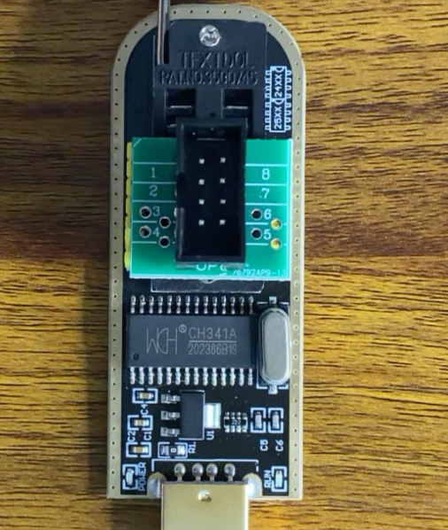
Then, you'll need to look at the NOR flag on the PCB, if its a cheap IoT device there should be only one. If you see multiple ones, you'll need to note down the label on the chip and do your research and check the datasheets, make sure what is the purpose of the chip.

Once you have the right one, you'll need to place the SOIC8 Clip. Remember, the pin number one has the red wire, and is label with a little circle on the chip itself.
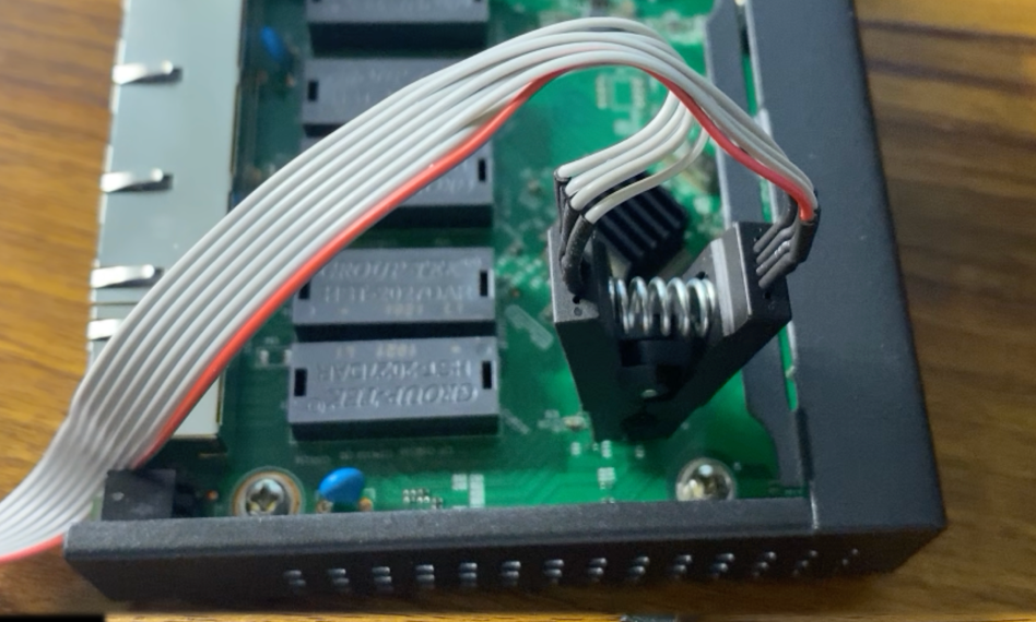
Since we are doing this while the chip is on the PCB, be aware that the Device will be powered on during the process.

Read it
Use the tool named Flashrom to read, analyze and extract the chip firmware into a binary file.
Identify the chip first
flashrom -p ch341a_spiRead twice and do a diff. A good dump is reproducible.
flashrom -p ch341a_spi -r dump1.bin
flashrom -p ch341a_spi -r dump2.bin
sha256sum dump1.bin dump2.bin
If the two reads do not match, your connection is marginal (clip contact, SoC contention, or voltage). Fix that before you trust the image. Once you have a stable dump, run it through binwalk exactly as in Method 1, a raw flash dump usually carries the bootloader, environment, kernel, and a SquashFS root all in one file.
Bonus Flipper Zero
If you have a flipper zero you don't use anymore, you can replace the CH341A with it using an external application.
Method 4: UART Bootloader Memory Dump
Most devices expose a serial console for factory debugging. Through it you often reach the bootloader (usually U-Boot) or a root shell, and from there you can read flash into RAM and print it out over the wire. Slower than a programmer, but it needs no desoldering and no clip.
What is UART?
UART (Universal Asynchronous Receiver/Transmitter) is a two-wire serial link for sending bytes one bit at a time. “Asynchronous” is the key word: there’s no clock line shared between the two sides. Instead, both ends agree in advance on how fast bits are sent. That agreed speed is the baud rate.
Baud rate = bits per second on the wire. 115200 baud means each bit lasts ~8.7 microseconds. Both sides must use the same rate; if they don’t, the receiver samples at the wrong moments and you get garbage (mojibake) on the console. Since there’s no clock to negotiate it, you often have to guess, common rates are 115200, 57600, 38400, 9600. A logic analyzer can measure the shortest pulse and tell you the rate directly.
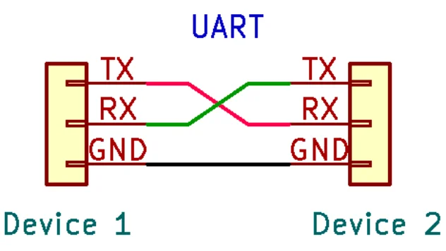
TX and RX are the two data lines:
TX (transmit): the pin a device sends data out of.
RX (receive): the pin a device listens on.
Find UART
Look for a header or a row of pads with four lines: VCC, GND, TX, RX. To identify them:
GND: continuity to the board's ground plane / shield.
VCC: sits at a steady 3.3V (do not connect this to your adapter).
TX: spikes with activity at boot, then idles high.
A logic analyzer or a multimeter in continuity/voltage mode sorts them out in a minute.
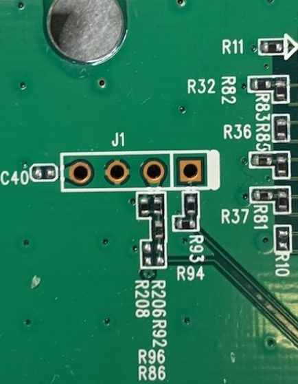

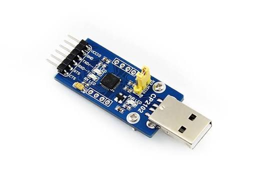
Connect a 3.3V USB-TTL adapter, TX to RX, RX to TX, GND to GND, and leave VCC disconnected. Match your adapter's logic level to the board (3.3V almost always; never 5V on a 3.3V UART).
Open the console
Common baud rates are 115200 and 57600. 8 data bits, no parity, 1 stop bit.
picocom -b 115200 /dev/ttyUSB0
# or: screen /dev/ttyUSB0 115200
Power the device and watch the boot log.


U-Boot usually prints a line like "Hit any key to stop autoboot", press a key in that window to drop to the bootloader prompt. (Random key, SPACE or CTRL+C)

Dump Flash from U-BOOT
U-Boot can copy flash into RAM and then display RAM, which is how you exfiltrate the image over serial. The exact commands vary by board, but the pattern is:
Inspect the environment and layout
help
printenv
For raw SPI/NAND: copy a region from flash into RAM, then dump RAM
sf probe 0                 # init the SPI flash
sf read 0x80000000 0x0 0x1000000  # read 16MB from flash offset 0 into RAM
md.b 0x80000000 0x1000000       # memory display: print those bytes as hex
md.b (memory display, byte-wide) streams the region to the console as a hex dump. Capture the whole serial session to a log file, then rebuild the binary from the hex on your host:
picocom/screen can log to a file your session. Afterwards, strip the addresses/ASCII columns and convert hex back to bytes
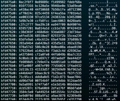
cat capture.log | <your md.b parser> > firmware.binThis is tedious at serial speed, a 16MB dump over 115200 baud takes a long while, but it is dependable and leaves no marks on the board
Root shell? No problem.
Some devices drop you straight to a Linux prompt. Then it is trivial, read the MTD partitions directly and push them off the box:
cat /proc/mtd                  # list partitions and sizes
cat /dev/mtd0 > /tmp/mtd0.bin  # or use nanddump for NAND
You can then exfiltrate the file over the network if you have one, or else base64 over the console:
base64 /tmp/mtd0.bin           # paste the output, decode on your host
openssl base64 -in mtd0.bin -out mtd0.b64 # if base64 not installed
Bonus Flipper Zero
Again, if you have a flipper zero and some wires, you can use it as a USB-Bridge with the official firmware. Check the GPIO menu and USB Serial.
More informations here : GPIO & Modules

Choosing a Method and What Comes Next
Work top to bottom. Each method is a fallback for the one above it.
Method | Effort | Risk to device | When it works |
Vendor download | Minutes | None | Image is published and not encrypted |
Intercept update | Minutes | None | Device fetches updates over cleartext or without cert pinning |
SPI flash dump (CH341A) | Minutes/Hours | Medium (voltage, rework) | External SPI flash, download failed or encrypted |
Minutes/Hours | Low | Serial console present, no clip or rework possible |
Once you have a raw image, the real work starts:
recursively extract filesystems
binwalk -Me firmware.binthen inspect the extracted root filesystem
find _firmware.bin.extracted -name '*.conf' -o -name 'passwd' -o -name 'shadow'From the extracted filesystem: pull the bootloader environment and partition map, locate the root filesystem (usually SquashFS), and start reading /etc, the web root, and any custom binaries. Hunt for credentials and keys, then load the interesting binaries into a disassembler or emulate the services under QEMU to fuzz them off-device.
Published by Exploit Security in The Exploit Society. Adrien Lasalle on getting firmware off an IoT device you own or are authorized to test, and why that binary is the first thing a hardware assessment needs.
What is The Exploit Society? The guest series on the Exploit Security blog.
Writers do not work here. The topics are theirs.
Why extract firmware? He argues you cannot audit what you cannot read. The image holds the web server, the TLS stack, hardcoded credentials and the vendor’s own scripts. Static analysis, secret hunting and off-device emulation all start once that file is in your hands. Where does he start? With the least destructive option that works: a vendor download, then an update intercepted in transit, then the flash chip, then a UART console. He is explicit that these techniques are for devices you own or are authorized to test, and that a 5V programmer on a 1.8V part kills the chip. Who published this? Exploit Security, a CREST-approved offensive security practice in Sydney offering penetration testing services and offensive security consultancy.
The author is Adrien Lasalle, a hardware hacker and maker.
For those aspiring Hardware Hackers be sure to check out the Damn Vulnerable Raspberry Pi developed by the team at Exploit Security.

Comments