UART (Universal Asynchronous Receiver-Transmitter)
- Victor Hanna

- May 9, 2023
- 5 min read
Updated: Dec 10, 2025

In this blog post we will be describing the hardware communications protocol known as Universal Asynchronous Receiver-Transmitter or simply UART. We will dive into the physical specifications and also how it can be used by security researchers when examining hardware being tested.
In this post we will cover the following:
Overview
Physical Interface
Data Transmission
UART Packet Format
How UART can be used by Security Researchers
Overview
UART is a ubiquitous device-to-device hardware communication protocol and hardware specification used to provide a method for interconnection of two devices across a 2-wire physical medium. Typically, UART is used for device management. UART utilizes a serial communications protocol, meaning that communication flows a single bit at a time over a physical medium at a pre-defined rate, known as the BAUD rate. The BAUD rate is what makes UART asynchronous, as both communicating end points are required to be pre-configured with the same transfer and receive rate in order to successfully communicate. An asynchronous configuration is required as UART does not utilise a single common clock for either of the end points to synchronize to.
Physical Interface
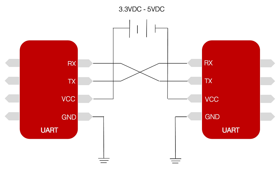
The physical interface used with UART consists of two wires for communications, namely TX (Transmit) and RX (Receive). When utilising UART as a point to point connection between two UART end points, it is necessary for connections to be made as illustrated below. Under normal operations VCC and GND are facilitated by the board that the chips are attached to, UART devices tend to operating at between 3.3VDC and 5VDC. VCC allows for a reference voltage across the TX line for times that the communication flows are at idle, where the transmit line is held high (Logic 1). When data is ready to be transmitted the TX line is then pulled to ground (Logic 0) prior to the commencement of data transfer. At this stage when the RX line detects the logic 0, the receiving peripheral prepares to start reading data in.
Data Transmission
UART uses a serial data transmission type, meaning that data to be sent and received is serialized into a single stream of 0's and 1's across a physical medium. In order for UART data to be serialized, typically the transmitter is connected to a common data bus, parallel data is sent through to the UART device 8 bits at a time. In order to buffer the incoming parallel communications, the UART uses shift registers to hold data for transmission and for receive. These shift registers are connected to the Tx and Rx lines of the UART and typically hold 8 bits of data at any one time. When 8 bits have populated the Rx shift register these 8 bits of data are moved into the read buffer register which is read by the CPU for further transfer to its ultimate destination. Likewise data is populated into the Tx shift register which then gets loaded into the Holding Register. Data in the Tx Holding Register is then shifted out over the Tx line one bit at a time. Typically the reads and writes to these registers are handled by the associated device drivers.
Communication data transmission is controlled by Start and Stop bits, which are governed by the associated BAUD rate, which both ends of the communications must pre-agreed upon prior to communication flows. The BAUD rate itself merely tells either side the intended amount of bits to be sent and received over a given second. This allows for correct interpretation of the data within the serialized communications. This allows either side of the communications to correctly understand where in the serialized data a Start bit occurs and likewise where Stop bit shall be.
UART Packet Format

Start Bit
The UART Tx line is kept high when no data is being transmitted
The UART Tx line is then pulled low for one clock cycle, when data is to be transmitted
The corresponding attached UART Rx line listens for this low signal and then starts reading the bit in the data frame
Data Frame
This is the actual data to be sent/received
Without a parity bit set 9 data bits can be used
With a parity bit set 5 to 8 data bits can be used
Frame is sent least significant bit first
Parity Bit
Used for integrity checks for data
Stop Bit
The sending device pulls the Tx line from low to high to signify the end of data transmission
How UART can be used by security researchers
The holy grail of many security research ventures is access to a UART interface. Using such an interface can afford a security researcher great benefits, such as access to the devices command line or additionally access to the startup boot process, which often can help illuminate many wonderful insights.
Accessing a UART interface - Example
A UART interface's typical footprint comes in the form of a four pin header or alternatively four test points without a header attached (Figure 3).

Once a UART interface has been located a security researcher will then be required to investigate the testpadds in order to ascertain which pins correspond to Ground, Tx and Rx. A multimeter set to continuity is the best way to do this.
The following steps outline the process:
1. Verify the ground pin using the continuity setting of a mulitmeter. Using a known ground as a reference point, attach a probe to the known ground point and the second probe to each one of the testpads until an audible beep is heard. (NOTE: DO NOT POWER DEVICE IN THIS STEP)

2. Verify the Tx and Rx pins using the DC voltage setting of a multimeter. Set the multimeter to read DC voltage within a 5VDC range (most common range). With the negative probe attached to the newly found ground pin attach the positive probe to each other pin respectively, whilst simultaneously powering on the device. Typically the Tx pin voltage shall fluctuate, this most commonly indicates data transmission across that pin. Using a process of elimination both the Tx and Rx pins can be identified using this rudimentary methodology.
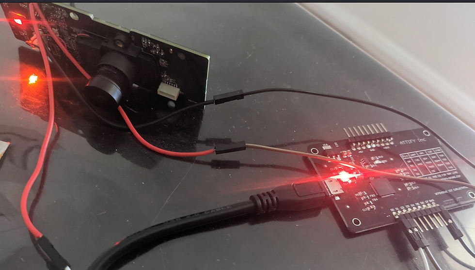
Now that we have identified the appropriate PIN-outs for the UART interface, a security researcher can now attach a intermediate bridge in order to interact with the devices UART. This bridge will be typically connected to a researchers notebook/PC across its USB, with the corresponding Tx connect to the peripheral devices Rx and likewise the corresponding Rx connected to the peripheral devices Tx. And of course Ground to Ground.
PRO Tip: Raspberry Pi's are great for this purpose, amongst other things
Recommended Bridges/Cables:
Part No: TTL-232R-3V3
JTAGulator (Grand Idea Studio), overkill but awesome kit
ATTIFY Badge
With the PINOUTs identified and an adequately spec'd bridge/cable at your disposal it is now time to wire in to the UART interface. This can either be done through soldering onto the testpads or alternatively using testprobes to achieve the same goal.
Now for the moment of truth, once all connections have been made power on your device. Ensure that you are using a terminal program such as SCREEN, Putty or Minicom to capture data as it traverses the wire.
PRO Tip: Ensure that your BAUD rate is correctly selected, otherwise unreadable unicode shall prevail !
Summary
This post intended to lay the foundations with respects to UART and its fundamental inner workings. In providing an overview of the architecture and its core features it is the hope that this information was found to be a valuable reference point. Like SPI, UART is also a ubiquitous technology within the embedded system ecosystem and knowledge of its functionality can prove to be another useful candidate in a security researchers toolkit.


Comments