Serial Peripheral Interface (SPI)
- Victor Hanna

- Feb 2, 2023
- 5 min read
Updated: Dec 10, 2025

In this blog post we will be describing what Serial Peripheral Interface or SPI, is and where and why it is used within embedded systems. This interface type is widely used and therefore understanding its functionality will assist whilst conducting security research.
The post shall attempt to describe:
An overview of SPI
SPI Main/Subnode architecture
SPI Data transmission
SPI Transmission Modes
How SPI can be used by security researchers
Dumping Flash via SPI
Summary
Overview
SPI is a full-duplex synchronous data transfer architecture used to transfer data between an embedded MCU (Micro Controller Unit) and a respective peripheral device or more generically between a Main and Subnode. Examples of such peripheral devices are sensors, SRAM (Static Random Access Memory), display controllers and NOR flash peripherals. As described above, SPI uses a full-duplex communications flow which is made possible through the use of separate send and receive lines. This allows peripherals that are attached to the corresponding SPI bus to both transmit and receive simultaneously. To achieve full-duplex data flows, SPI uses 4 unidirectional wires with each wire dedicated to a specific signal.

Figure 1. SPI Main/Subnode Interconnect

Figure 2. SPI 4-Wire annotation
SPI Main/Subnode Architecture
The architecture that is used by SPI is the Main/Subnode Architecture. The Main indicates the device that generates the clock signal. This SPI Clock signal is used to synchronise data transmission between the Main and each Subnode. As just inferred an SPI system can be made up of a single Main with multiple Subnodes. In order for the Main to indicate which Subnode it would like to interact with the Chip Select wire is first needed to be asserted. The Chip Select wire is asserted by electronically pulling the wire to a low signal (logic 0) and conversely pulled high (logic 1) when requiring disconnection to the subnode. The MOSI and MISO wires are the data lines used by an SPI system. MOSI describes the data line where data flows from the Main to Subnode, whereas the MISO describes the data line where data flows from the Subnode to Main. As mentioned above these flows can occur simultaneously in a full-duplex fashion.
SPI Data transmission
Data transmission is initiated by the Main, which sends a clock signal and asserts the appropriate chip select wire connected to the intended Subnode it wishes to transmit and receive data to and from. In order for data to be sent and received, each respective device will send (shift out) data across the MOSI data line for transmission and receive (sampled and read-in) data in across the MISO data line.
There are 4 SPI transmission modes that can be used for data transmission of which all four should be supported by the Main, however this is not the case for Subnodes, which will typically be pre-configured with a transmission mode. In the context of embedded systems, this is an initial design choice by the manufacturer, and ensures that all devices communicating over the SPI bus are compatible. The SPI Control Register stores the functional state of the transmission mode using two bits, namely the Clock Polarity bit (CPOL) and the Clock Phase bit (CPHA).
The CPOL bit refers to the logic level of the clock at idle, where idle is the state in which no data is being transmitted or received and where the Chip Select line is pulled high (active low configuration). The CPHA bit refers to the sampling edge, which indicates when data will be read-in or shifted-out on either the rising or falling edge of the clock pulse. In order for successful data transfer to take place all of these configurations should match at both ends of the data transfer lines.

Figure 3. Clock Polarity and Phase Diagram
SPI Transmission Modes
As mentioned above there are four SPI transmission modes. It is important to understand that although transmission modes are the basis for data transfer each device that is being controlled will have its own protocol format that allows for successful interaction with the device itself. This section is merely how basic SPI functions under-the-hood, however rest assured that manipulating a device of a specific type is where the curiosity truly grows.
Mode 0 - CPOL = 0, CPHA = 0
Every clock pulse transition to low transmits next bit
Every clock pulse phase transition to high samples data

Mode 1 - CPOL = 0, CPHA = 1
Every clock pulse transition to high transmits next bit
Every clock pulse phase transition to low samples data

Mode 2 - CPOL = 1, CPHA = 0
Every clock pulse transition to high transmits next bit
Every clock pulse phase transition to low samples data

Mode 3 - CPOL = 1, CPHA = 1
Every clock pulse transition to low transmits next bit
Every clock pulse phase transition to high samples data

If you examine things closely you will notice a correlation between both Mode 0 and 3 which are seemingly functionally identical, with the difference being starting clock logic levels. So to are Mode 1 and Mode 2.
How SPI can be used by security researchers
More often than not security researchers of embedded systems will often place high value on retrieval of a devices firmware. In some cases this firmware can be obtained from either a manufacturers website or alternatively via over the air firmware updates. In some cases these strategies may be elusive and may call for a more directed approach. One such highly successful approach is the extraction of firmware from flash memory. Flash memory is a non-volatile memory type that is most often the repository for an embedded systems' firmware. Firmware is essentially the bridge between the hardware of a system and the software drivers that allow for a system to function. It can also be bundled with the systems kernel and as such provides a treasure trove of information that underlies the system itself. Moreover if obtained can be used alongside an emulator to emulate the very function of the embedded system itself. Obtaining the running firmware of an embedded system can also open up possibilities like implementation of root kits or affording the opportunity to reverse engineer binaries to understand the inner workings and perhaps even research said binaries to tease out weaknesses.
Dumping Flash via SPI - Example
This example shows that once a PCB has been examined and an appropriate candidate flash memory chip has been identified, that it is then trivial to hookup to the peripheral and subsequently dump its contents.
Step 1. Identification of the peripheral
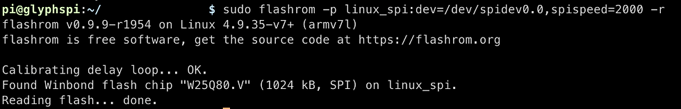
Examination of the PCB leads the researcher to understand that we are dealing with a Winbond flash memory chip (W25Q80DV). With this information on board a datasheet is obtained so as to ascertain pinouts of the chip

Step 2. Obtain Datasheet and identify pinouts
After obtaining the respective datasheet the determination is made of the peripherals pinouts

Step 3. Hookup to the respective pins and with the help of a trusted interface shield with corresponding GPIO's e.g. RPi, it can be then possible to dump the flash memory contents

Step 4. Using the flashrom utility to dump the flash for further testing
Summary
This post intends to lay the foundations with respects to SPI and its inner workings. In providing an overview of the architecture and its core features it is the hope that this information was found to be a valuable reference point. SPI is a technology that is ubiquitous with respects to the embedded system ecosystem and knowledge of its functionality can prove to be a useful candidate in a security researchers toolkit.


Comments